Loading...
Searching...
No Matches
devices::WinBond< CS > Class Template Reference
SPI device driver for WinBond flash memory chips, like W25Q80BV (8 Mbit flash). More...
#include <fastarduino/devices/winbond.h>
Inheritance diagram for devices::WinBond< CS >:

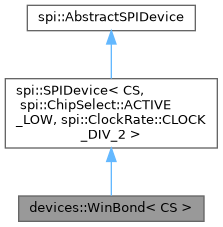
Collaboration diagram for devices::WinBond< CS >:
Classes | |
| struct | Device |
| Device information (§6.2.31) More... | |
| struct | Status |
| This type maps WinBond Status register (§6.1) to more readable pieces. More... | |
Public Types | |
| enum class | BlockProtect : uint16_t { BLOCK_NONE = 0x00 , BLOCK_UPPER_64KB = 0x01 << 2 , BLOCK_UPPER_128KB = 0x02 << 2 , BLOCK_UPPER_256KB = 0x03 << 2 , BLOCK_UPPER_512KB = 0x04 << 2 , BLOCK_LOWER_64KB = 0x09 << 2 , BLOCK_LOWER_128KB = 0x0A << 2 , BLOCK_LOWER_256KB = 0x0B << 2 , BLOCK_LOWER_512KB = 0x0C << 2 , BLOCK_ALL = 0x07 << 2 , BLOCK_UPPER_4KB = 0x11 << 2 , BLOCK_UPPER_8KB = 0x12 << 2 , BLOCK_UPPER_16KB = 0x13 << 2 , BLOCK_UPPER_32KB = 0x14 << 2 , BLOCK_LOWER_4KB = 0x19 << 2 , BLOCK_LOWER_8KB = 0x1A << 2 , BLOCK_LOWER_16KB = 0x1B << 2 , BLOCK_LOWER_32KB = 0x1C << 2 } |
| This enum provides information about block protection (bits BP0-2, TB and SEC of Status register, §6.1.3, §6.1.4 & §6.1.5) in a more readable way. More... | |
| enum class | StatusRegisterProtect : uint16_t { SOFTWARE_PROTECTION = 0x0000 , HARDWARE_PROTECTION = 0x0080 , POWER_SUPPLY_LOCKDOWN = 0x0100 } |
| This enum provides information about the method of write protection of the Status register itself (bits SRP0-1 of Status register, §6.1.7). More... | |
Public Member Functions | |
| WinBond ()=default | |
| Create a new device driver for a WinBond chip. | |
| Status | status () |
| Get the value of the chip's Status register (§6.1, §6.2.8). | |
| void | set_status (uint16_t status) |
| Change the Status register (only writable bits, §6.2.9). | |
| bool | wait_until_ready (uint16_t timeout_ms) |
| Wait until any erase or write operation is finished. | |
| void | power_down () |
| Set the chip to low power mode (§6.2.29). | |
| void | power_up () |
| Release power-down mode (§6.2.30). | |
| Device | read_device () |
| Get device informaton §6.2.31). | |
| uint64_t | read_unique_ID () |
| Get chip unique ID (§6.2.34). | |
| void | enable_write () |
| Enable write mode for the chip (§6.2.5). | |
| void | disable_write () |
| Disable chip write mode (§6.2.7). | |
| void | erase_sector (uint32_t address) |
Erase the sector (4KB) at address (§6.2.23). | |
| void | erase_block_32K (uint32_t address) |
Erase the block (32KB) at address (§6.2.24). | |
| void | erase_block_64K (uint32_t address) |
Erase the sector (64KB) at address (§6.2.25). | |
| void | erase_chip () |
| Erase the whole chip memory (§6.2.26). | |
| void | write_page (uint32_t address, uint8_t *data, uint8_t size) |
| Write data (max 256 bytes) to a page (§6.2.21). | |
| uint8_t | read_data (uint32_t address) |
| Read one byte of flash memory (§6.2.10). | |
| void | read_data (uint32_t address, uint8_t *data, uint16_t size) |
| Read several bytes of flash memory (§6.2.10). | |
Additional Inherited Members | |
 Protected Member Functions inherited from spi::SPIDevice< CS, spi::ChipSelect::ACTIVE_LOW, spi::ClockRate::CLOCK_DIV_2 > Protected Member Functions inherited from spi::SPIDevice< CS, spi::ChipSelect::ACTIVE_LOW, spi::ClockRate::CLOCK_DIV_2 > | |
| SPIDevice () INLINE=default | |
Create a new SPIDevice; this sets up the CS pin for later use during transfers. | |
| void | start_transfer () |
| Start an SPI transfer to this device. | |
| void | end_transfer () INLINE |
| End the current SPI ransfer tot hsi device. | |
| Protected Member Functions inherited from spi::AbstractSPIDevice | |
| AbstractSPIDevice (const AbstractSPIDevice &)=delete | |
| AbstractSPIDevice & | operator= (const AbstractSPIDevice &)=delete |
| uint8_t | transfer (uint8_t data) |
| Transfer one byte to the currently selected SPI slave device through MOSI pin, and get the byte returned by the device through MISO pin. | |
| void | transfer (uint8_t *data, uint16_t size) |
| Transfer an array of payload data to the currently selected SPI slave device through MOSI pin, and get all data bytes simultaneously received from that device through MISO pin. | |
| void | transfer (const uint8_t *data, uint16_t size) |
| Transfer an array of payload data to the currently selected SPI slave device through MOSI pin; any data bytes simultaneously received from that device through MISO pin are lost. | |
| void | transfer (uint8_t *data, uint16_t size, uint8_t sent) |
Transfer the provided byte sent several times to the currently selected SPI slave device through MOSI pin, and get all data bytes simultaneously received from that device through MISO pin. | |
| void | transfer (uint16_t size, uint8_t sent) |
Transfer the provided byte sent several times to the currently selected SPI slave device through MOSI pin; any data bytes simultaneously received from that device through MISO pin are lost. | |
Detailed Description
template<board::DigitalPin CS>
class devices::WinBond< CS >
class devices::WinBond< CS >
SPI device driver for WinBond flash memory chips, like W25Q80BV (8 Mbit flash).
- Template Parameters
-
CS the output pin used for Chip Selection of the WinBond chip on the SPI bus.
Member Enumeration Documentation
◆ BlockProtect
template<board::DigitalPin CS>
|
strong |
◆ StatusRegisterProtect
template<board::DigitalPin CS>
|
strong |
Member Function Documentation
◆ status()
template<board::DigitalPin CS>
|
inline |
◆ set_status()
template<board::DigitalPin CS>
| void devices::WinBond< CS >::set_status | ( | uint16_t | status | ) |
◆ wait_until_ready()
template<board::DigitalPin CS>
| bool devices::WinBond< CS >::wait_until_ready | ( | uint16_t | timeout_ms | ) |
Wait until any erase or write operation is finished.
This method continuously reads the Status register and check the BUSY bit (§6.1.1). If the chip is busy, then the method yields time, i.e. put the MCU to sleep according to the default board::SleepMode.
- Parameters
-
timeout_ms the maximum time, in milliseconds, to wait for the chip to be ready
- Return values
-
true if the chip is ready false if the chip is still busy after timeout_msdelay
◆ power_down()
template<board::DigitalPin CS>
|
inline |
◆ power_up()
template<board::DigitalPin CS>
|
inline |
◆ read_device()
template<board::DigitalPin CS>
| WinBond< CS >::Device devices::WinBond< CS >::read_device | ( | ) |
◆ read_unique_ID()
template<board::DigitalPin CS>
| uint64_t devices::WinBond< CS >::read_unique_ID | ( | ) |
◆ enable_write()
template<board::DigitalPin CS>
|
inline |
◆ disable_write()
template<board::DigitalPin CS>
|
inline |
◆ erase_sector()
template<board::DigitalPin CS>
|
inline |
Erase the sector (4KB) at address (§6.2.23).
- Parameters
-
address address (24 bits) of the sector to erase
- See also
- enable_write()
◆ erase_block_32K()
template<board::DigitalPin CS>
|
inline |
Erase the block (32KB) at address (§6.2.24).
- Parameters
-
address address (24 bits) of the sector to erase
- See also
- enable_write()
◆ erase_block_64K()
template<board::DigitalPin CS>
|
inline |
Erase the sector (64KB) at address (§6.2.25).
- Parameters
-
address address (24 bits) of the sector to erase
- See also
- enable_write()
◆ erase_chip()
template<board::DigitalPin CS>
|
inline |
Erase the whole chip memory (§6.2.26).
- See also
- enable_write()
◆ write_page()
template<board::DigitalPin CS>
|
inline |
Write data (max 256 bytes) to a page (§6.2.21).
- Parameters
-
address address (24 bits) of the first flash byte to write data the data to be written to the flash page at address;datamay be overwritten by this operation.size the number of bytes to write; if 0, then 256 bytes (one full page) will be written.
◆ read_data() [1/2]
template<board::DigitalPin CS>
| uint8_t devices::WinBond< CS >::read_data | ( | uint32_t | address | ) |
◆ read_data() [2/2]
template<board::DigitalPin CS>
| void devices::WinBond< CS >::read_data | ( | uint32_t | address, |
| uint8_t * | data, | ||
| uint16_t | size | ||
| ) |
Read several bytes of flash memory (§6.2.10).
- Parameters
-
address address (24 bits) of the first flash byte to read data the buffer that shall receive the value of all read bytes; this must have been allocated at leat sizebytessize the number of bytes to read from flash memory
The documentation for this class was generated from the following file:
- fastarduino/devices/winbond.h