There are plenty of devices of all kinds, based on I2C interface, that you may want to connect to your Arduino or a board you created with an AVR ATmega or ATtiny MCU.
If you want to learn more about I2C concepts and vocabulary, you can find further information on Wikipedia.
Unfortunately, FastArduino obviously cannot provide specific support for all existing I2C devices.
However, based on a given device datasheet, it can be quite easy to add a FastArduino driver for any I2C device.
FastArduino provides all the necessary classes and methods for you to implement such a specific driver.
The following sections describe the FastArduino API for I2C device driver implementation, and list the steps to successfully implement such a driver.
FastArduino I2C driver API
The generic support for I2C device driver in FastArduino looks quite simple, it is entirely embedded in one class, i2c::I2CDevice; this is a template class which all actual I2C device drivers shall derive from.
This template class has only one MANAGER parameter, which must be kept as is in all subclasses; this represents the type of I2C Manager used to handle the I2C bus and operations.
The i2c::I2CDevice class mainly contains protected types aliases and methods to create and launch read and write commands to a device on the I2C bus.
Any FastArduino I2C device must be able to work in both asynchronous and synchronous modes The i2c::I2CDevice API is made for asynchronous operations; synchronous flavours of a specific device API are based on asynchronous implementations of that API (just awaiting for the operation to finish).
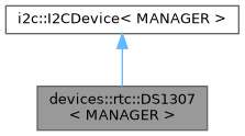
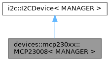
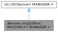
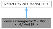
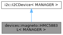
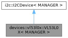
As you can see in the following diagrams, the drivers for I2C devices currently supported by FastArduino directly derive from i2c::I2CDevice:
- DS1307 Real Time Clock chip
- MCP23008 8-Bit I/O Expander chip
- MCP23017 16-Bit I/O Expander chip
- MPU6050 3D Accelerometer-Gyroscope chip
- HMC5883L 3D Compass chip
- VL53L0X Time of Flight ranging sensor
Creating a new driver for an I2C device must follow these steps:
- Create a
i2c::I2CDevicetemplate subclass; let's call itMyI2CDevicein the rest of this page. - Redefine (as
private) the following type aliases inherited fromi2c::I2CDevice:PARENT,FUTURE - Add a
publicconstructor with one argument:MyI2CDevice::MyI2CDevice(MANAGER& manager)whereMANAGERis a class template argument of bothMyI2CDeviceandi2c::I2CDevice; this constructor must call the inherited constructor and pass it 3 arguments:manager, the default I2C address for your device, and finally, one ofi2c::I2C_STANDARDori2c::I2C_FASTconstants, to indicate the best mode (highest I2C frequency) that your device can support. - List the API you need to provide to the end user of your device (based on the device datasheet)
- For each
publicAPI you need to provide, define a specific Future to hold values written to the device, as well as values later read from the device. Each defined Future shall derive fromFUTURE(type alias defined above). This future will allow asynchronous execution of the API. FastArduino guidelines for I2C devices suggest to name the future class according to the API name itself e.g.SetDatetimeFuturefor theset_datetime()API. - For each
publicAPI, define a method that takes a reference to the future defined above and return anint. The implementation of this method is based on mainly 3 inheritedprotectedmethods:i2c::I2CDevice.read(),i2c::I2CDevice.write()andi2c::I2CDevice.launch_commands(). In simple situations, there are even simpler methods that your I2C device API can call:i2c::I2CDevice.async_read(),i2c::I2CDevice.sync_read(),i2c::I2CDevice.async_write()andi2c::I2CDevice.sync_write(). - For each
publicAPI, also define a similar method (same name) with a synchronous flavour. That method will directly take "natural" arguments (no futures) as input or output (reference), and return aboolto indicate if API was performed without any error.
I2CDevice API
Before describing FastArduino I2C Device API, it is important to mention that this API is heavily based on FastArduino future API, which concepts shall be first understood before starting to build your own support for an I2C device.
Subclassing i2c::I2CDevice gives MyI2CDevice access to all low-level protected aliases:
PARENT: this is simply defined asi2c::I2CDevice<MANAGER>and is useful for accessing next aliasesi2c::I2CDevice::FUTURE: this is the type of Future used byMANAGER; it must be used for defining your own Future types for all asynchronous API ofMyI2CDevice
Note that to be accessible from MyI2CDevice class, these types must be redefined as follows:
i2c::I2CDevice constructor takes 4 arguments:
MANAGER& manager: this should be passed as is fromMyI2CDeviceconstructoruint8_t device: this is the default I2C address of this device (this 7-bits address must be already left-shifted one bit to leave the LSB available for I2C direction read or write)Mode<MODE> mode(MODEis a template argument of the constructor,i2c::I2CMode MODE): this should be passed one of 2 constantsi2c::I2C_FASTori2c::I2C_STANDARD) to indicate the best I2C mode (highest frequency) supported byMyI2CDevice: this will impact whatMANAGERtype can be used when instantiatingMyI2CDevicetemplatebool auto_stop: this defines whether all chains of commands ofMyI2CDeviceshall automatically be ended with a STOP condition on the I2C bus or not. In most cases, the default (false) should work, but some devices (e.g. DS1307) do not work properly if 2 chains of commands are not separated by a STOP condition.
Note that device address must be provided at construction time but can optionally be changed later. Regarding its I2C address, typically an I2C device falls in one of the following categories:
- it has a fixed I2C address that cannot be changed (e.g. DS1307 RTC chip)
- it has an I2C address that can be changed by hardware (e.g. jumpers) among a limited range of possible addresses (e.g. MCP23017 I/O expander chip, MPU 6050 acceleromete/gyroscope chip)
- it has a fixed default I2C address that can be changed by software (e.g. VL53L0X "micro lidar" chip); this is generally a bit harder to support (extra API to implement for your I2C device).
For devices in category 1, you would typically define the address as a constant in MyI2CDevice and pass it directly to i2c::I2CDevice constructor.
Here is a snippet from DS1307 device:
For devices in category 2, you would rather define an enum class limiting the possible addresses configurable by hardware, or pass the address (as uint8_t) to the driver class constructor.
For devices in category 3, you would first define the fixed default address as a constant, then define an API to change it (as a data member of MyI2CDevice).
Subclassing i2c::I2CDevice gives MyI2CDevice access to all low-level protected methods:
i2c::I2CDevice.read(uint8_t read_count, bool finish_future, bool stop): create a command to read bytes from the I2C device; read bytes will be added to the related Future (passed tolaunch_commands())i2c::I2CDevice.write(uint8_t write_count, bool finish_future, bool stop):create a command to write bytes to the I2C device; written bytes are taken from the related Future (passed tolaunch_commands())i2c::I2CDevice.launch_commands(ABSTRACT_FUTURE& future, initializer_list<> commands): prepare passed read/writecommandsand send them toMANAGERfor later asynchronous execution (commands are queued); theFuturereferenced byfutureis used to provide data to write to, and store data to read from, the I2C device.i2c::I2CDevice.set_device(uint8_t device): change the I2C address of this device. This is useful for devices that allow changing their I2C address by software.
Note that read() and write() methods do not actually perform any I2C operation! They only prepare an I2C read or write command (i2c::I2CLightCommand type embedding necessary information) based on their arguments:
read_count/write_countspecify the number of bytes to read or write. When0(the default), this means that all bytes (as defined in the specific Future) will be read or written.finish_future: specify that, after this command execution, the Future assigned to the current transaction will be marked as finishedstop: specify that, after this command execution, an I2C STOP condition will be generated on the I2C bus; this will automatically trigger a "START" condition on the next command (whether it is part of the current chain of commands or not)
The launch_commands() method does the actual work:
- with a synchronous I2C Manager, it blocks until all commands get executed or an error occurs; the assigned Future is directly
READY(or inERROR) when the method returns - with an asynchronous I2C Manager, it enqueues all commands for asynchronous execution and returns immediately; the assigned Future will be later updated (it status will become either
READYorERROR) once all commands are complete.
In addtion to low-levels methods discussed above, i2c::I2CDevice also provides the following higher-level methods that will make it even simpler to use for simple cases:
i2c::I2CDevice.async_read(F& future, bool stop = true): start an asynchronous read of future which type isF(template argument of the method)i2c::I2CDevice.sync_read(T& result): start a synchronous read through future which type isF(1st template argument of the method) and await for result of typeT(2nd template argument of the method)i2c::I2CDevice.async_write(F& future, bool stop = true): start an asynchronous write of future which type isF(template argument of the method)i2c::I2CDevice.sync_write(const T& value): start a synchronous write of value of typeT(2nd template argument of the method) through future which type isF(1st template argument of the method) and await until write is finished.
All these methods are based on low-level methods but they make the implementation of your device API a blaze (one-liner for each API method). These methods work in simple situations which typically represent most cases you will have to deal with for a given I2C chip:
- read is made of a write part followed by a read part (in the same I2C transaction)
- write is made only of a write part
As long as your API fits in these situations, those high-level API can apply. Here is an example excerpted from DS1307 device implementation:
In this snippet you see 4 one-liner examples showing each high-level read/write methods.
Although each of these methods is a template, only the "sync" flavours require explicit template argument for the Future used. Indeed, sync methods need to instantiate the future and cannot "guess" the future type to instantiate.
Those high-level methods will not be used in the case where you need several writes or several reads in the same I2C transaction. For instance, the MPU6050 device has some cases where several write commands must be processed but with a "REPEAT START" condition in between:
In that snippet, BeginFuture is prepared to:
- write 3 consecutive registers (1 byte each), starting at
CONFIGregister - write 1 register (1 byte), at
PWR_MGMT_1register
begin() implementation then calls launch_commands() with 2 distinct write commands.
I2C device registers common operations
Most I2C devices API consist in reading and writing device registers at a specific address (referenced by a byte); registers may be one byte long or more depending on what each register represents.
In order to simplify support of new I2C devices, FastArduino comes with a few extra utilities that can greatly speed up device support implementation.
These utilities are in header i2c_device_utilities.h in the same i2c namespace as I2CDevice abstract base class.
The following template classes are defined in there:
ReadRegisterFutureandTReadRegisterFuture: future classes to read one register of any type of value; type conversion is possible by providing aFUNCTORclass or function.WriteRegisterFutureandTWriteRegisterFuture: future classes to write one register of any type; type conversion is possible by providing aFUNCTORclass or function.I2CFuturesGroup: abstract future allowing its derived classes to aggregate several futures used in the same I2C transaction; this is useful when dealing with particularly complex I2C devices.I2CSameFutureGroup: instances of this class will generate one-byte register writing I2C transactions from content (register id and register value) stored in Flash; this is useful when dealing with some I2C devices that need long initialization process from hard-coded values.
The DS1307 RTC device is a good example of TReadRegisterFuture and TWriteRegisterFuture simple usage, along with conversion functors:
The VL53L0X Time-of-Flight laser device is much complex and makes heavy use of advanced utilities like I2CFuturesGroup:
We see in the above example the future SetGPIOSettingsFuture that aggregates 5 futures to write values to distinct registers. Device method set_GPIO_settings() shows the peculiar way to start I2C commands directly through the future.start() method.
I2C Bus handling
Handling of the I2C bus by the I2C Manager and the I2CDevice follows standard I2C protocol, with some level of "intelligence".
In usual conditions: launch_commands() can execute long chains of commands on one device:
- The first command in the chain will generate a "START" condition on the I2C bus as required by the I2C protocol
- By default, all following commands will be preceded by a "REPEAT START" condition on the I2C bus
- By default, the last command in the chain will not end with a "STOP" condition on the bus; FastArduino I2C Manager will keep the I2C bus for itself, unless required otherwise by I2C devices implementation.
This default behaviour allows your I2C device API implementation to perform a sequence of calls to the I2C device, where the first call will acquire the bus, and all following calls in between will not need to acquire the bus.
You can change the default for each command or for a whole device:
- at command level, by setting
stopargument totrue, which will produce a "STOP" condition at the end of that command and a "START" condition on the next command in the chain. - at device level, by setting
auto_stopconstructor argument totrue; then all chains of commands for the device will always end with a STOP condition.
IMPORTANT: Actually, asynchronous flavours of I2C Managers will release the I2C bus at the end of an I2C transaction, in case there is no more pending command (from another I2C transaction) in the commands queue.
API Typical Example
For many I2C devices, communication is based on writing and reading "registers", each device having its own list of specific registers. Hence most I2C device drivers API will consist in reading or writing one register.
In FastArduino, drivers like devices::mcp230xx::MCP23008 first define private generic Future classes, later used by specific API to read registers:
In this snippet, a base Future, ReadRegisterFuture, is defined. It will serve as a base class for all specific Futures needed by all API reading registers, like in the following excerpt from MCP23008 device:
In the above code, we heavily depend on I2C device utilities: GetValuesFuture is just defines as an alias based on TReadRegisterFuture for register address GPIO; this allows callers of the values() API to directly instantiate this Future without further input.
The implementation of values() is a one-liner that requires no further explanation.
A similar approach is used for writing a value to a device register and will not be detailed here.
Debugging support for a new device (low-level)
In general, before developing a full-fledged driver for an I2C device, you need to learn how to use that device.
Based on the device datasheet, you first learn how to manipulate the device through the I2C bus.
For better understanding, you generally use a debugging example that helps demonstrate how the device works.
One easy way to develop such a debugging sample is to create a program with just one source code file containing:
- proper
#includedirectives - a
PublicDeviceclass that derives fromi2c::I2CDevicebut declaresmain()as afriend, which allows direct calls, frommain(), toprotectedAPI ofi2c::I2CDevice, for easy testing - directly call SPI API on a
PublicDeviceinstance, frommain()and trace results to a console, through UART - use, as I2C Manager,
I2CSyncDebugManagerorI2CSyncDebugStatusManager, which allow tracing (live or later) all steps of I2C transactions
FastArduino includes such a debugging sample in examples/i2c/I2CDeviceProto example, copied hereafter:
This example is just an empty skeleton for your own tests. It is made of several parts:
Those lines include a few headers necessary (or just useful) to debug an I2C device.
Any specificity of the tested I2C device is defined as a constant in the next code section. Note the definition of DEVICE_ADDRESS constant: this 7-bit I2C device address is shifted one bit left as an 8th bit will be added (I2C communication protocol) to define data direction for each transmission.
This section defines various types aliases, for I2C Manager, I2C debugger, and types used as part of device API definition. In addition, a DEBUG macro to debug all I2C steps after API execution is defined.
Then an output stream is created for tracing through UART, and the necessary UART ISR is registered. Also, we declare that no future listener is used; this is needed because you shall use futures in your tests. Note that if you use complex futures, you may need to register future listeners, but that is for complex I2C devices only (e.g. VL53L0X).
This is where we define a utility class to debug our I2C interface to the tested device. PublicDevice class does nothing but making all protected methods callable from main(), so that we can directly perform our code tests in main(), without thinking much about proper API design now.
This is the main() function where it all happens. First we initialize the MCU and the UART for tracing.
Here we simply initialize I2C function on the UNO.
We then declare the device variable that we will use for testing our I2C device.
Finally the rest of the code is placeholder for any initialization API, followed by an infinite loop where you can call sync_read/sync_write or launch_commands/read/write methods on device in order to test the way to handle the target device.
Defining the driver API based on device features
At this level, you have already been able to debug how the device works and you have a good overview of what features you want to provide to developers (and to yourself as the first of all) who will want to use this device.
An easy way is to provide an API that maps every feature found in the datasheet to its dedicated method. This is what we would call a low-level API; that is the minimum your driver should provide.
Additionally MyI2CDevice might implement a higher level API, based on the low-level one, but this is not mandatory; actually, this is not even advised generally, as this high-level API might be implemented in a distinct class. Using a separate class for high-level API allows other developers to develop their own high-level API without having to use yours if it does not fit their needs.
It is often advised to add begin() and end() methods to MyI2CDevice when it makes sense. begin() would initialize the device before usage (most devices will require special setup before use).
Implementing the driver API
This step consists in implementing the API defined in the step before.
Typically every API will be made of:
- a specific Future class that encapsulates input arguments (in its constructor) and holds place for output; this Future shall embed any necessary conversion of input arguments if needed, as well as conversion of output, through override of
get()method - one asynchronous method taking as only argument a reference to the Future defined above, and calling either low-level
I2CDevicemethods (launch_commands(), withwrite()andread()calls to prepare I2C commands), or high-level methods (async_read(),async_write()), as described above - one synchronous method taking same arguments as Future constructor defined above, plus a reference argument for any output; this method instantiates the above Future, calls the asynchronous method defined before, and awaits the Future to be ready and get its output; another simpler option could use high-level methods (
sync_read(),sync_write()).
Previous sections provide snippets.
The last mile: add driver to FastArduino project!
Bravo! You successfully added FastArduino support, in your own project, for a specific I2C device!
The last mile would now consist in adding your valuable work to FastArduino library! You do not have to, of course, but this would be a good way to:
- thank other people who provided FastArduino open source library to you
- feel part of the community
- get feedback on your work, potentially allowing it to be further improved
- share your work with the rest of the world
However, like for a marathon, the last mile can be difficult! In order to run this last mile, you will have to:
- first accept FastArduino Apache License 2.0 for your contribution, or discuss with FastArduino owner for another one, if compatible
- follow FastArduino coding guidelines: this might impose some code rewrite or reformatting
- add API documentation with doxygen: this is mandatory for all
publicmethods, and advised forprotectedones. - add one (or more) usage example and integrate it in the
examples/i2cdirectory; examples must be kept simple but still demonstrate the API usage; example circuits (connection pins) shall be described. These examples can be further used as "tests" before new releases of FastArduino. - optionally develop a tutorial for this device
- prepare and propose a PR to FastArduino project
Important condition: in order to accept merging a PR to FastArduino, I must be able to check it by myself, hence I need to first have the new supported device available on my workbench; I will gladly buy one (or a few) if it is affordable and easy to find.