There are plenty of devices of all kinds, based on SPI interface, that you may want to connect to your Arduino or a board you created with an AVR ATmega or ATtiny MCU.
If you want to learn more about SPI concepts and vocabulary, you can find further information on Wikipedia.
Unfortunately, FastArduino obviously cannot provide specific support for all existing SPI devices.
However, based on a given device datasheet, it can be quite easy to add a FastArduino driver for any SPI device.
FastArduino provides all the necessary classes and methods for you to implement such a specific driver.
The following sections describe the FastArduino API for SPI device driver implementation, and list the steps to successfully implement such a driver.
FastArduino SPI driver API
The generic support for SPI device driver in FastArduino is quite simple, it is entirely embedded in 2 classes:
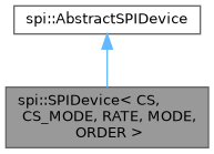
The important class here is spi::SPIDevice, this is a template class (with many parameters discussed later) which all actual SPI device drivers shall derive from.
The abstract base class AbstractSPIDevice contains most methods used in transferring (both ways) content to/from a device on the SPI bus. It exists solely for the sake of code size: it factors all methods that do not depend on any spi::SPIDevice template parameter, into a non-template class so that generated code is not repeated for each device driver. All its important methods are available directly from spi::SPIDevice and its children, as protected methods.
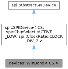
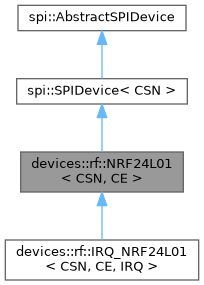
As you can see in the following diagrams, the drivers for SPI devices currently supported by FastArduino directly derive from spi::SPIDevice, sometimes enforcing template parameter values:
- Winbond SPI memory chip
- NRF24L01 SPI Radio-Frequency transmitter/receiver
Hence, creating a new driver for an SPI device is as simple as:
- Creating a
spi::SPIDevicesubclass; let's call itMySPIDevicein the rest of this page. - Add proper
publicAPI on thisMySPIDeviceclass, based on actual device features we want to use - Implement this API through the basic
protectedAPI methods inherited fromspi::SPIDevice
SPIDevice template parameters
The spi::SPIDevice template class is instantiated through the following template parameters:
- CS: this
board::DigitalPinis the most important parameter of the template; it defines on which digital pin of the MCU the targeted device "chip select" pin shall be connected; inMySPIDevice, this shall remain a template parameter because you never know in advance how the device will be connected to the MCU across different projects. - CS_MODE: this parameter defines if the CS pin is active HIGH or LOW (the default); this is specific to every SPI device and shall be forced to the proper value in
MySPIDeviceclass definition. - RATE: this parameter fixes the SPI clock frequency to the maximum value supported by the actual device. This is actually a divider of the MCU clock, used to provide the actual SPI frequency. Note that the proper selection for this template parameter depends on the maximum transfer rate supported by the target device and the MCU frequency used in your project.
- MODE: one of the 4 SPI modes (as explained here and there); typically a given device supports exactly one mode, you should thus enforce the proper mode for your target device.
- ORDER: this parameter defines the order in which bits of a byte are transferred: MSB (most significant bit) first, or LSB (least significant bit) first; typically a given device supports exactly one bit transfer order, you should thus enforce the proper order for your target device.
SPIDevice API
Subclassing spi::SPIDevice gives MySPIDevice access to all low-level protected methods:
spi::SPIDevice.start_transfer(): any SPI transfer to the slave SPI device must start with this call. Such a transfer must end by callingspi::SPIDevice.end_transfer().spi::SPIDevice.transfer(uint8_t): send one byte to the slave SPI device and return the byte that was received during transmission (SPI is a full-duplex protocol where master and slave can send data at the same time).spi::SPIDevice.transfer(uint8_t*, uint16_t): send a packet of bytes to the slave SPI device, and receive all bytes simultaneously transmitted by that device.spi::SPIDevice.transfer(const uint8_t*, uint16_t): send a packet of bytes to the slave SPI device, but trash any bytes simultaneously transmitted by that device.spi::SPIDevice.end_transfer(): finish the current transfer to the slave SPI device, that was initiated withspi::SPIDevice.start_transfer().
Any feature implementation in MySPIDevice will always consist in a sequence of calls to the methods above, like:
Most SPI devices use codes to perform various features, either write-only (sending values to the device) or read-only (asking the device for some values).
In the sections below, we will sometimes refer to a simple SPI device, the MCP3008, an 8-channel Analog-Digital Converter, which communication protocol is super simple (because the number of features for such a chip is quite limited).
Debugging support for a new device (low-level)
In general, before developing a full-fledged driver for an SPI device, you need to learn how to use that device.
Based on the device datasheet, you first learn how to manipulate the device through the SPI bus.
For better understanding, you generally use a debugging example that helps demonstrate how the device works.
One easy way to develop such a debugging sample is to create a program with just one source code file containing:
- proper
#includedirectives - a
PublicDeviceclass that derives fromspi::SPIDevicebut declaresmain()as afriend, which allows direct calls, frommain(), toprotectedAPI ofspi::SPIDevice, for easy testing - directly call SPI API on a
PublicDeviceinstance, frommain()and trace results to a console, through UART
FastArduino includes such a debugging sample in examples/spi/SPIDeviceProto example, copied hereafter:
This example demonstrates how to simply test the MCP3008 ADC chip. It is made of several parts:
Those lines include a few headers necessary (or just useful) to debug an SPI device.
Then a buffer is defined for tracing through UART and the necessary UART ISR is registered.
Any specificity of the tested SPI device is defined as a constant in the next code section. These constants will be used for template parameters later on.
Here we set the UNO pin to be connected to the CS pin of the tested SPI device, then we define the proper SPI clock rate for this device, based on CPU frequency and device maximum SPI frequency.
This is where we define a utility class to debug our SPI interface to the tested device. PublicDevice class does nothing but making all protected methods callable from main(), so that we can directly perform our code tests in main(), without thinking much about proper API design now.
This is the main() function where it all happens. First we initialize the MCU and the UART for tracing.
Here we simply initialize SPI function on the UNO.
We then declare the device variable that we will use for testing our SPI device.
Then we start an infinite loop that will read data from the SPI device and trace it:
In this code snippet, result1 and result2 each contain a part of the expected result (analog channel read on MCP3008), these must be used to calculate the actual value (based on the datasheet):
Defining the driver API based on device features
At this level, you have already been able to debug how the device works and you have a good overview of what features you want to provide to developers (and to yourself as the first of all) who will want to use this device.
An easy way is to provide an API that maps every feature found in the datasheet to its dedicated method. This is what we would call a low-level API; that is the minimum your driver should provide.
Additionally MySPIDevice might implement a higher level API, based on the low-level one, but this is not mandatory; actually, this is not even advised generally, as this high-level API might be implemented in a distinct class. Using a separate class for high-level API allows other developers to develop their own high-level API without having to use yours if it does not fit their needs.
It is often advised to add begin() and end() methods to MySPIDevice when it makes sense. begin() would initialize the device before usage (most devices will require special setup before use).
In the MCP3008 example, the API could be rather simple; for instance, we could:
- define an
enumfor the selection of channel to read (including single-ended Vs. differential input modes) - define a template class
MCP3008Deviceas device driver keeping onlyCSas template parameter - add only one API method
uint16_t read_channel()
Implementing the driver API
We proceed with the MCP3008 example. When implementing the API, you must scrupulously follow the device datasheet for every method!
Here is a simple implementation attempt for MCP3008 driver:
Note the implementation of read_channel() which is mainly the same as in the debugging example described earlier.
Of course, the MCP3008 is a very simple device which is easy to interact with through SPI, but there are many SPI devices with more complex capabilities (cameras, B&W and color display controllers, RF transmitters...) For those devices, the number of features can be large and this would result in dozens or even hundreds of API methods!
Support for ATtiny MCU
ATtiny MCU provides some support (through its USI feature) for SPI but it is quite limited in comparison to ATmega devices; hence FastArduino SPI support for ATtiny chips has similar limitations:
- The only
spi::DataOrdersupported isspi::DataOrder::MSB_FIRST - The only
spi::Modes supported arespi::Mode::MODE_0andspi::Mode::MODE_1 spi::ClockRateparameter is not used inspi::SPIDeviceimplementation, hence the maximum clock rate is always used, and is roughly equal toCPU frequency / 7, hence typically a bit more than 1MHz with common clock frequency used in ATtiny boards (internal 8MHz RC clock); this might be a problem for devices supporting only 1MHz SPI.
These limitations might prevent proper support, on ATtiny MCU, of some SPI devices.
If your device is in this situation, then you should add compile error checks (through static_assert(), or #if and #error) in your SPI device driver header file, so that it cannot compile for these unsupported ATtiny targets.
The last mile: add driver to FastArduino project!
Bravo! You successfully added FastArduino support, in your own project, for a specific SPI device!
The last mile would now consist in adding your valuable work to FastArduino library! You do not have to, of course, but this would be a good way to:
- thank other people who provided FastArduino open source library to you
- feel part of the community
- get feedback on your work, potentially allowing it to be further improved
- share your work with the rest of the world
However, like for a marathon, the last mile can be difficult! In order to run this last mile, you will have to:
- first accept FastArduino Apache License 2.0 for your contribution, or discuss with FastArduino owner for another one, if compatible
- follow FastArduino coding guidelines: this might impose some code rewrite or reformatting
- add API documentation with doxygen: this is mandatory for all
publicmethods, and advised forprotectedones. - add one (or more) usage example and integrate it in the
examples/spidirectory; examples must be kept simple but still demonstrate the API usage; example circuits (connection pins) shall be described. These examples can be further used as "tests" before new releases of FastArduino. - optionally develop a tutorial for this device
- prepare and propose a PR to FastArduino project
Important condition: in order to accept merging a PR to FastArduino, I must be able to check it by myself, hence I need to first have the new supported device available on my workbench; I will gladly buy one (or a few) if it is affordable and easy to find.